Getting Started
If it’s the first time you work with a VESC, you SHOULD consult senior members. If you forgot the steps, DO NOT attempt blindly. Doing so can cause severe bodily injury or death.
Verify Electronics Configuration
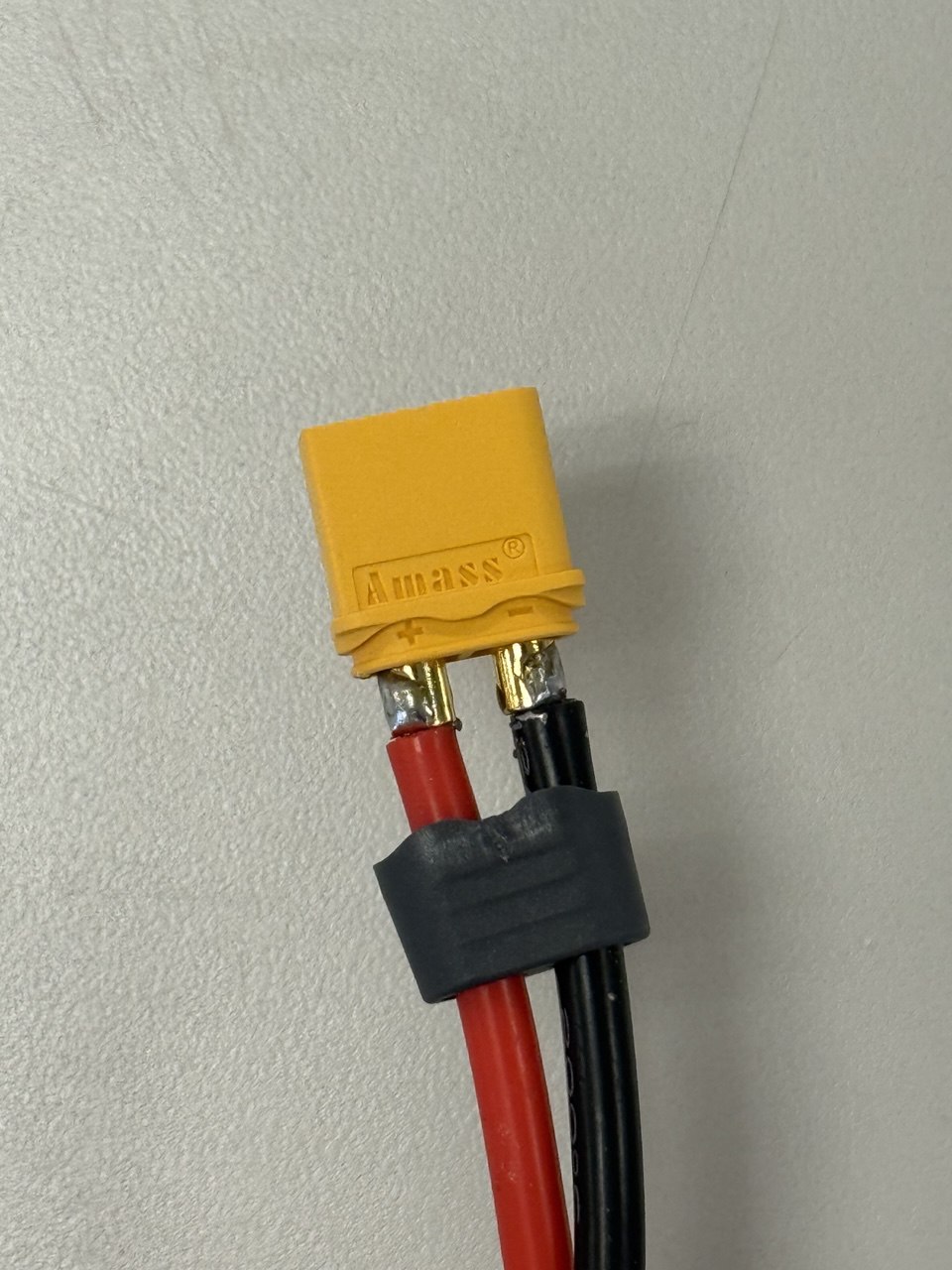
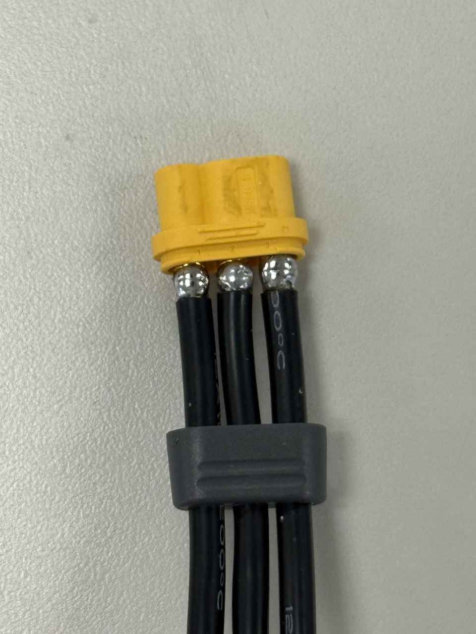
XT60 and MR60 Connectors
The 2-wire power input and three-phrase conenctors are XT60 and MR60 respectively.
If the protector is not capped, make sure:
- No short among any pins
- Red cable goes into the +ve socket and black cable into the -ve socket (XT60 only)
Use a vise or any tool of your choice to attach the protective cap afterwards.
Examples:
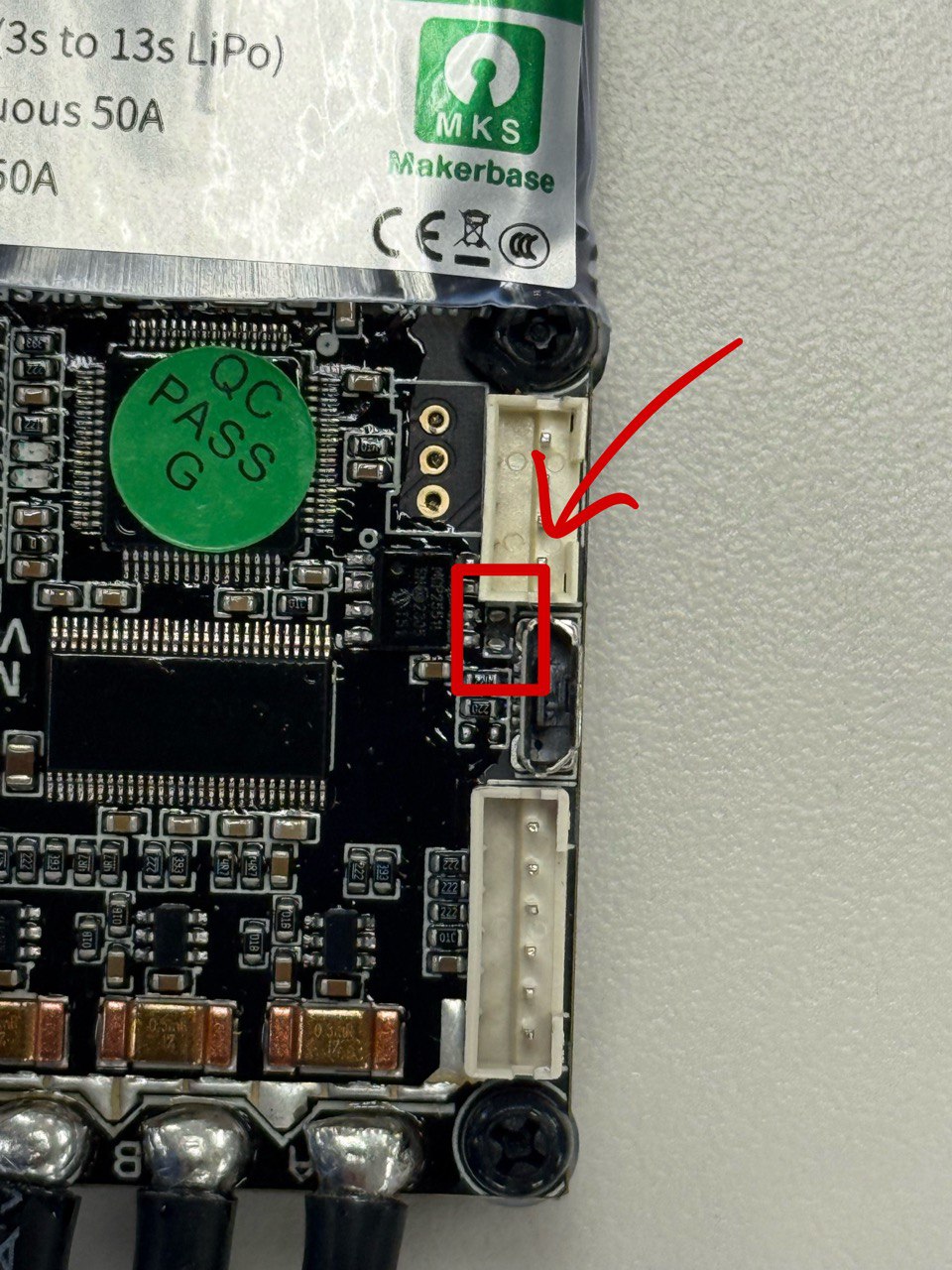
CAN Bus Termination Resistor
Make sure the CAN Bus termination resistor is removed as shown in the following image: